Study Guide
Alternating Current
-
University:
Concordia University Wisconsin -
Course:
PHYS 1524 | General Physics II Academic year:
2023
-
Views:
470
Pages:
28
Author:
Isabella Bolton
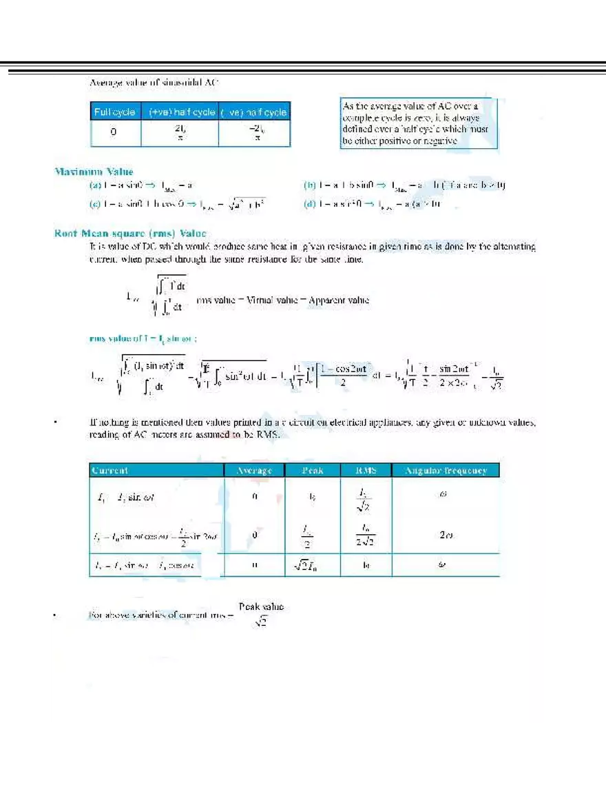
= 1 (V0 I0 sin 2 t cos V0 I0 sin t cos t sin )dt T 0 T T = V0 I0 1 sin 2 t cos dt 1 sin t cos t sin dt V0 I0 T0 T 0 Instantaneous V0 I0 cos = Vrms Irm,s cos 2 Average power/actual power/ Virtual power/ apparent power dissipated power/power loss Power/rms Power P = VI P = Vrms Irms cos P = Vrms Irms 1 2 cos 0 sin
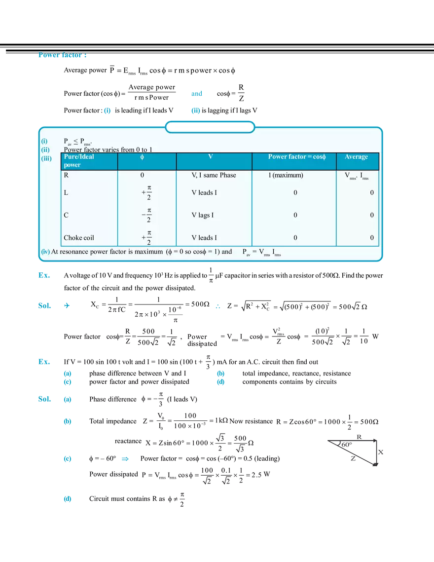
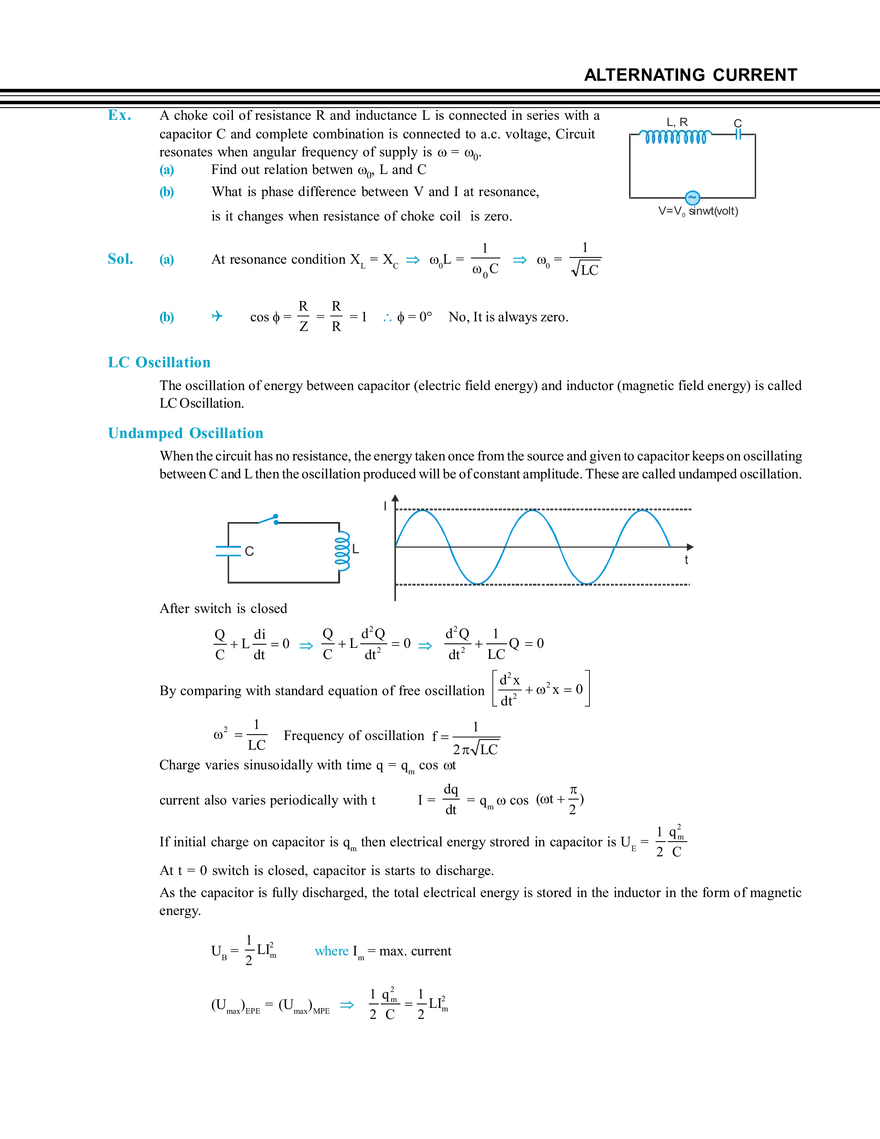
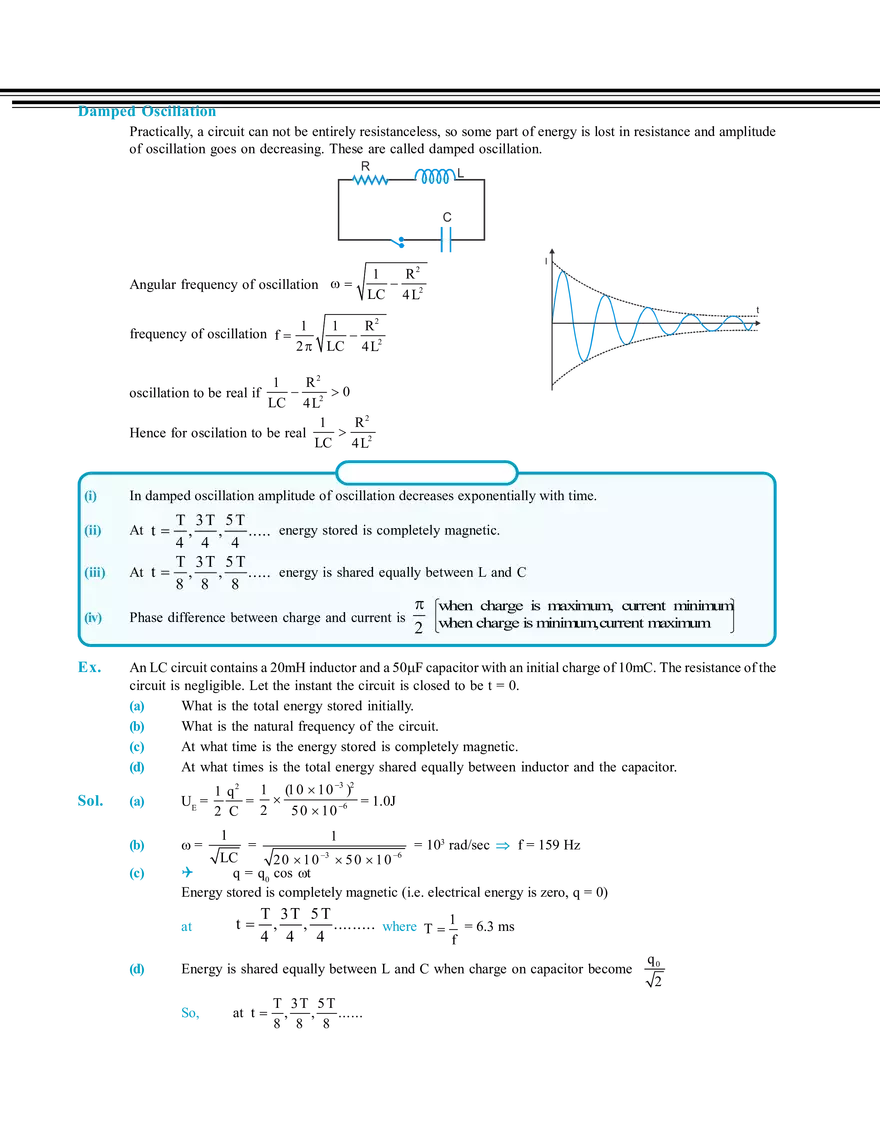
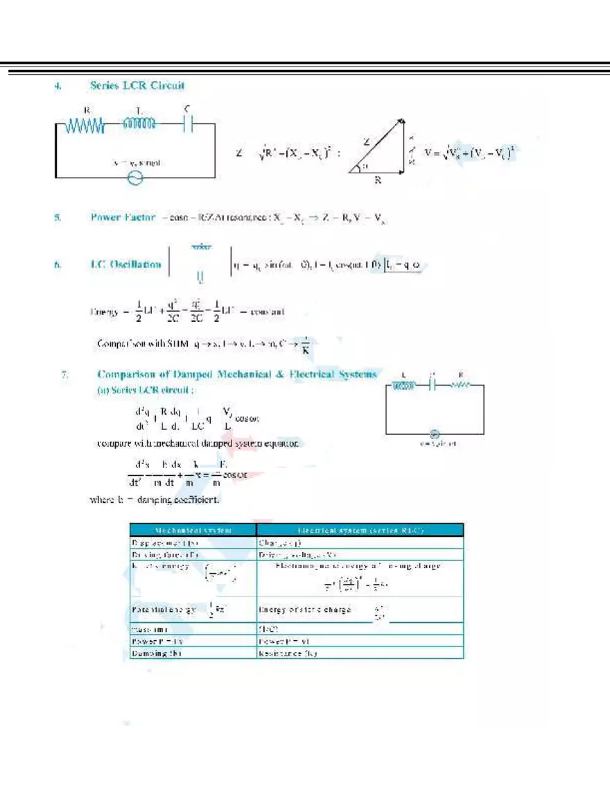
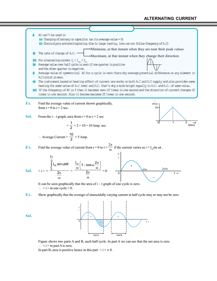
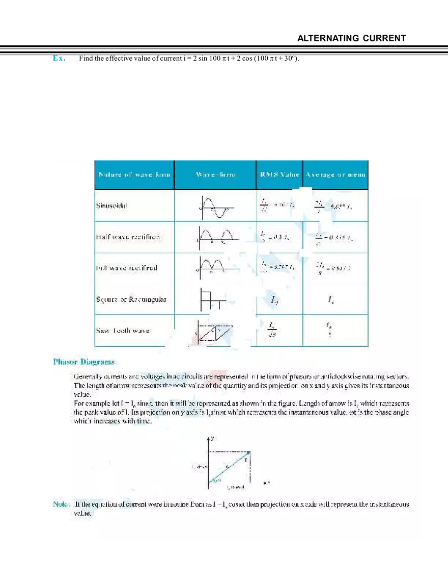
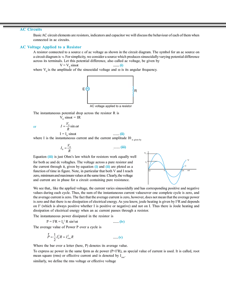
= Peak power P = V0 I0 (i) Irms cosis known as active part of current or wattfull current, workfull current. It is in phase with voltage. (ii) Irms sinis known as inactive part of current, wattless current, workless current. It is in quadrature (90) with voltage. Power factor : Average power P E rms Irms cos r m s power cos Power factor (cos ) Average power r m s Power and Power factor : (i) is leading if I leads V (i) (ii) (iii) cos= (ii) is lagging if I lags V Pav < Prms. Power factor varies from 0 to 1 Pure/Ideal Pure/Ideal power power R 0 V V V, I same Phase Vrms. Irms V leads I 0 0 C 2 V lags I 0 0 0 0 A voltage of 10 V and frequency 103 Hz is applied to XC 1 2 fC Power factor cos= Sol. 1 (maximum) 2 factor of the circuit and the power dissipated. Ex. Average Average V leads I 2 (iv) At resonance power factor is maximum (= 0socos= 1) and Sol. Power Power factor factor = = cos cos L Choke coil Ex. R Z 1 10 6 2 10 3 Pav = Vrms Irms 1 F capacitor in series with a resistor of 500. Find the power 50 0 Z = R 2 X2C (5 00 )2 (50 0 )2 50 0 2 (10 )2 1 1 R V2 5 00 1 = = Power = Vrms Irms cos rms cos = W 10 Z 5 00 2 Z 5 00 2 2 2 dissipated If V = 100 sin 100 t volt and I = 100 sin (100 t + ) mA for an A.C. circuit then find out 3 (b) total impedance, reactance, resistance (d) components contains by circuits (a) (c) phase difference between V and I power factor and power dissipated (a) Phase difference (b) Total impedance Z = (c) reactance X Zsin 6 0 10 00 3 5 00 2 3 = – 60° Power factor = cos = cos (–60°) = 0.5 (leading) (I leads V) 3 V0 10 0 1k Now resistance R Zcos 60 1 000 1 50 0 I0 1 00 1 0 3 2 Power dissipated P Vrms Irms cos (d) Circuit must contains R as 2 100 2 0.1 2 1 2.5 W 2 60° Z R X ALTERNATING CURRENT 1 when applied voltage is V = 100 sin 100t volt and resistance of circuit 2 is 200 then calculate the inductance of the circuit. Ex. If power factor of a R-L series circuit is Sol. cos = L = Ex. Sol. R 1 R = Z = 2R R 2 X2L = 2R XL 3 R Z 2 Z 3 R L= 3R = 3 200 2 3 H = 1 00 A circuit consisting of an inductance and a resistance joined to a 200 volt supply (A.C.). It draws a current of 10 ampere. If the power used in the circuit is 1500 watt. Calculate the wattless current. Apparent power = 200 × 10 = 2000 W Power factor cos = True power 1500 3 = = 2 0 0 0 4 Apparent power 2 Wattless current = rms sin = 10 Ex. Sol. 10 7 3 1 A 4 4 A coil has a power factor of 0.866 at 60 Hz. What will be power factor at 180 Hz. Given that cos = 0.866, = 2f = 2 × 60 = 120 rad/s, ’ = 2f’ = 2 × 180 = 360 rad/s Now, cos = R/Z R = Z cos = 0.866 Z But Z= R 2 (L)2 L = Z2 R 2 = Z2 (0 .8 6 6 Z)2 = 0.5 Z L = 0 .5 Z 0.5 Z = 120 When the frequency is changed to ’ = 2 × 180 = 3 × 120 = 300 rad/s, then inductive reactance ’ L = 3 L = 3 × 0.5 Z = 1.5 New impedance Z’ = New power factor = [R ' ( 'L)2 ] = (0.8 6 6 Z)2 (1 .5 Z)2 = Z [(0 .8 6 6 )2 (1.5 )2 ] = 1.732Z R 0 .8 66 Z = = 0.5 Z' 1.7 32 Z Choke Coil In a direct current circuit, current is reduced with the help of a resistance. tube light rod Hence there is a loss of electrical energy I2 R per sec in the form of heat in the resistance. But in an AC circuit the current can be reduced by choke coil which involves very small amount of loss of energy. Choke coil is a copper coil wound over a soft iron laminated core. This coil is put in series with the circuit in which current is to be reduced. It also known as ballast. starter choke coil Circuit with a choke coil is a series L-R circuit. If resistance of choke coil = r (very small) The current in the circuit I E Z with Z (R r)2 (L)2 So due to large inductance L of the coil, the current in the circuit is decreased appreciably. However, due to small resistance of the coil r, The power loss in the choke Pav = Vrms Irms cos 0 cos r Z r 2 2 2 r L r 0 L (i) Choke coil is a high inductance and negligible resistance coil. (ii) Choke coil is used to control current in A.C. circuit at negligible power loss (iii) Choke coil used only in A.C. and not in D.C. circuit (iv) Choke coil is based on the principle of wattless current. (v) Iron cored choke coil is used generally at low frequency and air cored at high frequency. (vi) Resistance of ideal choke coil is zero Ex. A choke coil and a resistance are connected in series in an a.c circuit and a potential of 130 volt is applied to the circuit. If the potential across the resistance is 50 V. What would be the potential difference across the choke coil. Sol. V= Ex. An electric lamp which runs at 80V DC consumes 10 A current. The lamp is connected to 100 V – 50 Hz ac source compute the inductance of the choke required. Sol. Resistance of lamp R V 80 8 I 10 VR2 VL2 VL V2 VR2 (13 0 )2 (50 )2 = 120 V Let Z be the impedance which would maintain a current of 10 A through the Lamp when it is run on V 100 100 Volt a.c. then.Z = = = 10 but Z = R2 I 10 (L)2 = Z2 – R2 = (10)2 – (8)2 = 36 L = 6 L = 6 6 = = 0.02H 2 50 Ex. Calculate the resistance or inductance required to operate a lamp (60V, 10W) from a source of (100 V, 50 Hz) Sol. (a) V Lamp + VR = 100 VR = 40V Now current througth Lamp is = But (b) R Maximum voltage across lamp = 60V VR= IR 40 = 10 1 Wattage = = A 6 0 6 voltage 100V, 50Hz 1 (R) R = 240 6 L Now in this case (VLamp)2 + (VL)2 = (V)2 (60)2 + (VL)2 = (100)2 VL = 80 V Also 100V, 50Hz 1 VL = IXL = XL so XL = 80 × 6 = 480 = L (2f) L = 1.5 H 6 A capacitor of suitable capacitance replace a choke coil in an AC circuit, the average power consumed in a capacitor is also zero. Hence, like a choke coil, a capacitor can reduce current in AC circuit without power dissipation. Cost of capacitor is much more than the cost of inductance of same reactance that's why choke coil is used. ALTERNATING CURRENT Ex. A choke coil of resistance R and inductance L is connected in series with a capacitor C and complete combination is connected to a.c. voltage, Circuit resonates when angular frequency of supply is = 0. (a) Find out relation betwen 0, L and C (b) What is phase difference between V and I at resonance, (a) At resonance condition XL = XC 0L = (b) cos = R R = = 1 = 0° Z R 1 0 = 0 C C ~ V=V0 sinwt(volt) is it changes when resistance of choke coil is zero. Sol. L, R 1 LC No, It is always zero. LC Oscillation The oscillation of energy between capacitor (electric field energy) and inductor (magnetic field energy) is called LC Oscillation. Undamped Oscillation When the circuit has no resistance, the energy taken once from the source and given to capacitor keeps on oscillating between C and L then the oscillation produced will be of constant amplitude. These are called undamped oscillation. I C L t After switch is closed Q d2 Q d2 Q 1 Q di L 2 0 Q 0 L 0 2 C LC dt dt C dt d2 x 2 By comparing with standard equation of free oscillation 2 x 0 dt 1 1 Frequency of oscillation f LC 2 LC Charge varies sinusoidally with time q = qm cos t 2 current also varies periodically with t I= dq = qm cos (t ) dt 2 If initial charge on capacitor is qm then electrical energy strored in capacitor is UE = At t = 0 switch is closed, capacitor is starts to discharge. 1 q 2m 2 C As the capacitor is fully discharged, the total electrical energy is stored in the inductor in the form of magnetic energy. UB = 1 2 LIm 2 where Im = max. current (Umax)EPE = (Umax)MPE 1 q 2m 1 2 LIm 2 C 2 Damped Oscillation Practically, a circuit can not be entirely resistanceless, so some part of energy is lost in resistance and amplitude of oscillation goes on decreasing. These are called damped oscillation. R L C Angular frequency of oscillation 1 R2 2 LC 4 L I t 1 1 R2 frequency of oscillation f 2 2 LC 4 L 1 R2 2 0 LC 4 L 1 R2 Hence for oscilation to be real LC 4 L2 oscillation to be real if (i) In damped oscillation amplitude of oscillation decreases exponentially with time. (ii) At t (iii) (iv) Ex. Sol. T 3T 5T , , ..... energy stored is completely magnetic. 4 4 4 T 3T 5T , ..... energy is shared equally between L and C At t , 8 8 8 Phase difference between charge and current is when charge is maximum, current minimum 2 when charge is minimum,current maximum An LC circuit contains a 20mHinductor and a 50F capacitor with an initial charge of 10mC. The resistance of the circuit is negligible. Let the instant the circuit is closed to be t = 0. (a) What is the total energy stored initially. (b) What is the natural frequency of the circuit. (c) At what time is the energy stored is completely magnetic. (d) At what times is the total energy shared equally between inductor and the capacitor. (a) 3 2 1 q 2 1 (1 0 10 ) UE = = = 1.0J 2 5 0 10 6 2 C (b) = (c) 1 = = 103 rad/sec f = 159 Hz 3 6 LC 20 10 5 0 1 0 q = q0 cos t Energy stored is completely magnetic (i.e. electrical energy is zero, q = 0) at (d) 1 t T 3T 5T , , ......... where T 1 = 6.3 ms 4 4 4 f Energy is shared equally between L and C when charge on capacitor become So, at t T 3T 5T , , ...... 8 8 8 q0 2 ALTERNATING CURRENT T 1. Average value I av Idt 0 T dt T T 1 Idt T0 RMS value 0 0 2 T dt 0 For sinusoidal voltage V = V0 sin t : Vav V0 2V0 & Vrms 2 For sinusoidal current I = I0 sin(t + ) : I av 2. I rms I dt I0 2I 0 & I rms 2 AC Circuits V I I I V V0 sin t R V I V I I V0 sin t 2 L V I I V I V0 Csin t 2 3. Impendance : Z = R 2 X 2 where X = reactance Series LCR Circuit Z = X = XL – XC 4. Z R 2 XL XC ; 2 V VR2 VL VC R 5. Power Factor = cos = R/Z At resonance : XL = XC Z = R, V = VR L 6. LC Oscillation q = q0 sin (t + ), I = I0 cos(t + ) I 0 q 0 C Energy = q2 1 1 2 q2 LI 0 LI02 = constant 2 2C 2C 2 Comparison with SHM q x, I v, L m, C 7. 1 K Comparison of Damped Mechanical & Electrical Systems (a) Series LCR circuit : V d 2 q R dq 1 q 0 cos t 2 dt L dt LC L compare with mechanical damped system equation F d 2 x b dx k x 0 cos t 2 dt m dt m m where b = damping coefficient. M e c h an i c al s ys te m D is p la c e me n t (x) D riv in g fo rc e (F ) K in e t ic e n e rg y El e c tr i c al s ys te m (s e r i e s R L C ) C h a rg e (q ) 1 2 mv 2 D riv in g v o lt a g e (V) Ele c t ro m a g n e t ic e n e rg y o f mo v in g c h a rg e 1 2 P o t e n t ia l e n e rg y ma s s (m ) 1 kx 2 2 dq L dt En e rg y o f s t a t ic c h a rg e (1/ C ) Po wer P = Fv P o w e r P = VI D a m p in g (b ) R e s is t a n c e (R ) 2 1 2 Li 2 q 2C 2 2 ALTERNATING CURRENT (b) Parallel LCR circuit : In this case I = IL + IC + I R = V dd dd 11dd dd2 11 dd 11 CC 2 0sin sint t LL dtdt dtdt RRdtdt dt RC RC dt 2 LC LC ZC ZC Displacement (x) Flux linkage () dx Velocity dt d Voltage dt Mass (m) Capacitance (C) Spring constant (k) Reciprocal Industance (1/L) Damping coefficient (b) Reciprocal resistance (1/R) Driving force (F) Current (i)
Related Documents
- Latent Heat: Hidden Energy In Phase Transitions
- Law Of Conservation Of Energy In Energy Balance
- Work - Physics Notes
- Vector Subtraction: Method and Application
- Elastic Collision in One Dimension
- Vertical Projection
- Equations of Uniformly Accelerated Motion
- Arithmetic Operations with Significant Figures
- Application of Dimensional Analysis
- Energy - Physics Study Notes
- Time Period of Satellite
- Characteristics of Gravitational Force
- Measuring Heat Of Formation Co2 Experiment Data
- Stopping Time - Notes for Physics
- Berzelius Vital Force Theory
- Questions And Answers - Newton'S Law Of Cooling
- Newton'S Law Of Cooling
- Stefan'S Law
- Questions And Answers - Perfect Black Body
- Adiabatic Processes: Energy Analysis In Isolated Systems
Alternating Current


Recommended Documents

Get your assignment done in just 3 hours. Quick, easy, and available 24/7.


Report
Tell us what’s wrong with it:
Thanks, got it!
We will moderate it soon!
Report
Tell us what’s wrong with it:
Free up your schedule!
Our EduBirdie Experts Are Here for You 24/7! Just fill out a form and let us know how we can assist you.
Take 5 seconds to unlock
Enter your email below and get instant access to your document